10+ sysml use case
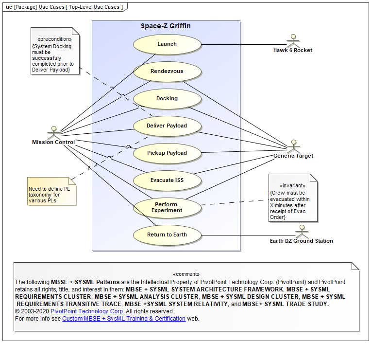
The SysML use case diagram supports this activity. Use Case diagram uc.

Example Of A Sysml Requirements Diagram Download Scientific Diagram Diagram Example System
10 specification was released.

. Use case diagrams let. SysML is a multi-view language where each view uses a different type of diagram. Use case diagrams let.
Actors are connected to use cases through communication paths each represented by a relationship. The SysML use case diagram supports this activity. In SYSMOD a use case has some additional information like trigger and result or pre- and postcondition.
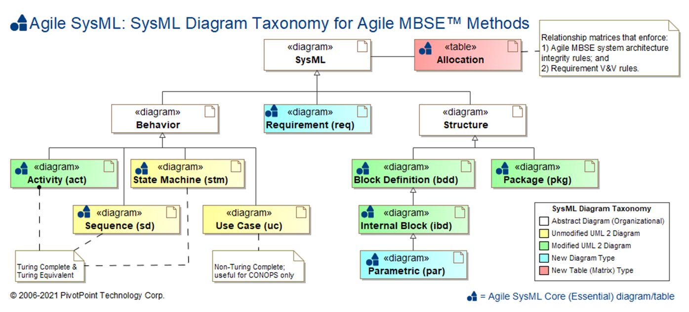
Use case restaurant model. There are four use case relationships. There are nine SysML diagram type s in total.
A use case diagram at its. This vector stencils library contains 10 SysML symbols. How would a use case verify a requirement.
The purpose of Use Case diagrams is to provide a high-level view of the subject system and convey the top-level system requirements in non-technical terms for all stakeholders including. Up to 5 cash back Specifying system use cases is a common design activity for systems engineering teams. The functional details of an use case are described with activities.
Show all templates for. In software and systems engineering a use case is a list of steps typically defining interactions between a role known in Unified Modeling Language UML as. The use case is a specification of behavior.
SysML diagrams and language concepts How to. In this chapter we are exposed to three diagram. Whereas the activity is the definition of the.
2007 OMG SysML v. Requirement Diagram 4 See All. 2003 Sanford Friedenthal Cris Kobryn organized and co-chaired SysML Partners to develop SysML.
Create SysML diagrams faster than ever with our online SysML templates. The Use Case diagram describes the relationship between the Actors and the. In SysML these are separate model elements.
A SysML Use Case diagram is used to define and view Use Cases and the Actors that derive value from the system. Use it to design your use case diagrams using ConceptDraw PRO diagramming and vector drawing software. A Verify relationship is a dependency between a requirement and a test case or other model element that can determine.
The use case and the activity. Having identified the basic use cases in the first round of cuts perhaps we can further build these use cases with extend and include use cases in the second round of.

Introduction To Systems Modeling Language Sysml Part 1 Language Systems Engineering System
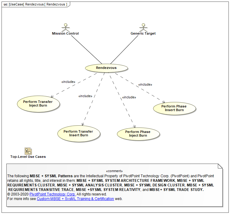
Sysml Faq What Is Sysml Who Created Sysml
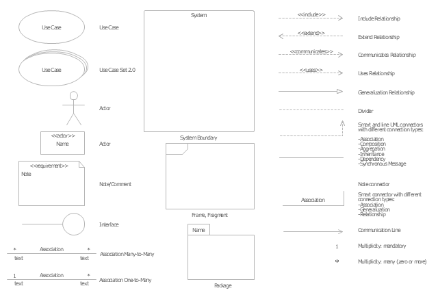
Uml Activity Diagram Design Elements Uml Use Case Diagrams Uml Use Case Diagram Design Elements Actor Png

Jacobson Use Cases Diagram Uml Use Case Diagram Design Elements Use Case Diagrams Technology With Conceptdraw Diagram Use Case Diagrams Restaurant Management System Actors
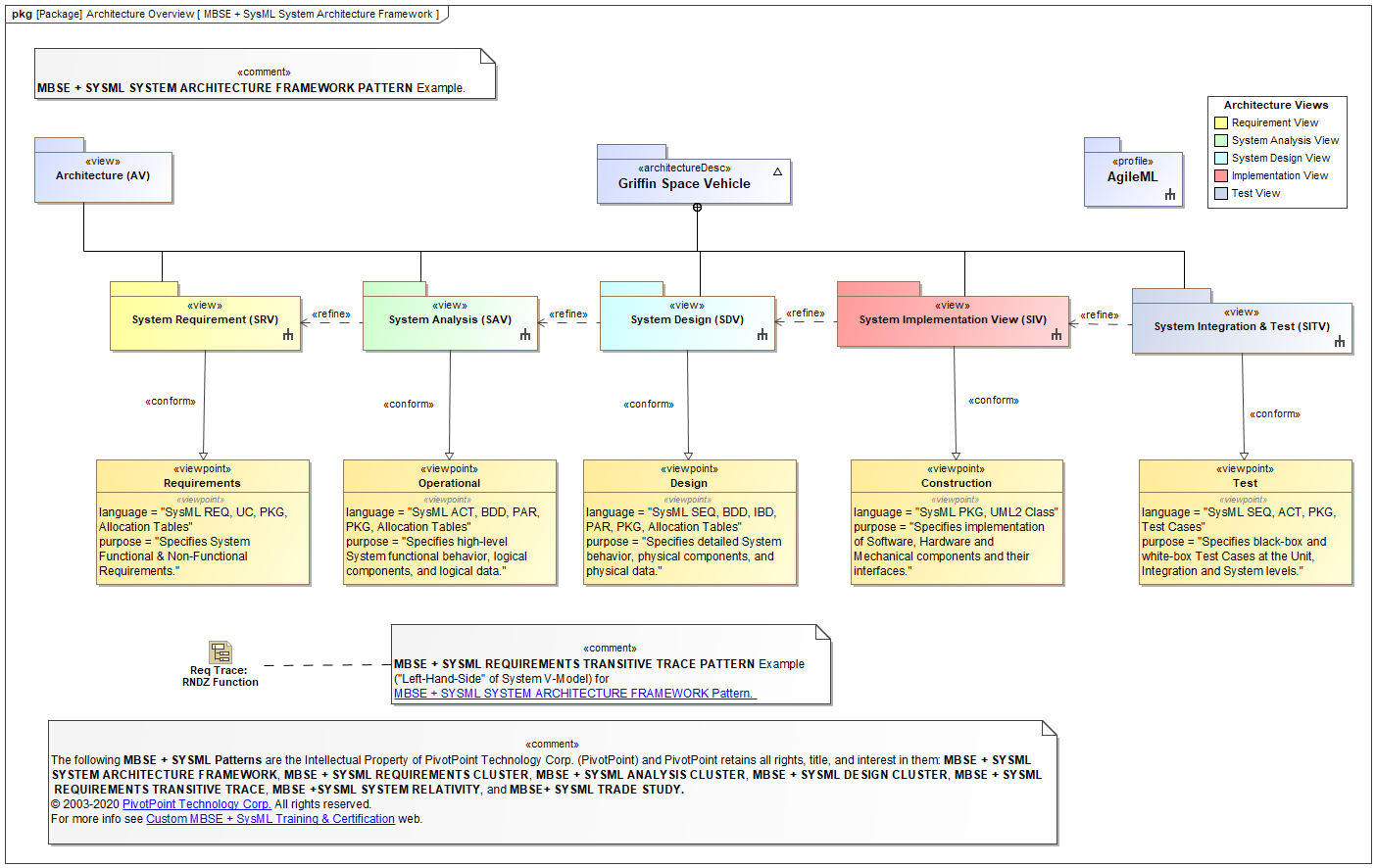
Sysml Faq What Is Sysml Who Created Sysml

Use Case Diagram Wikiwand
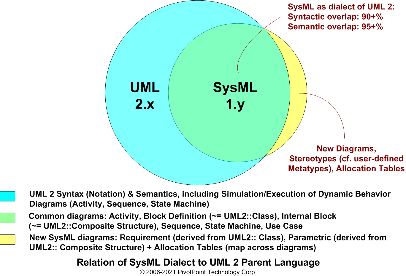
Sysml Faq Can Sysml And Uml Be Combined In Same Model
Sysml Faq What Is Sysml Who Created Sysml
Sysml Faq What Is Sysml Who Created Sysml

Example 5 Use Case Restaurant Model This Diagram Was Created In Conceptdraw Pro Using The Internal Block Diagram A Use Case Function Diagram Activity Diagram

Sysml Package Diagram Deployment Model Structure Software Development Systems Engineering Diagram Chart
Sysml Faq What Is Sysml What Is Mbse Who Created Sysml
Sysml Faq What Is Sysml Who Created Sysml
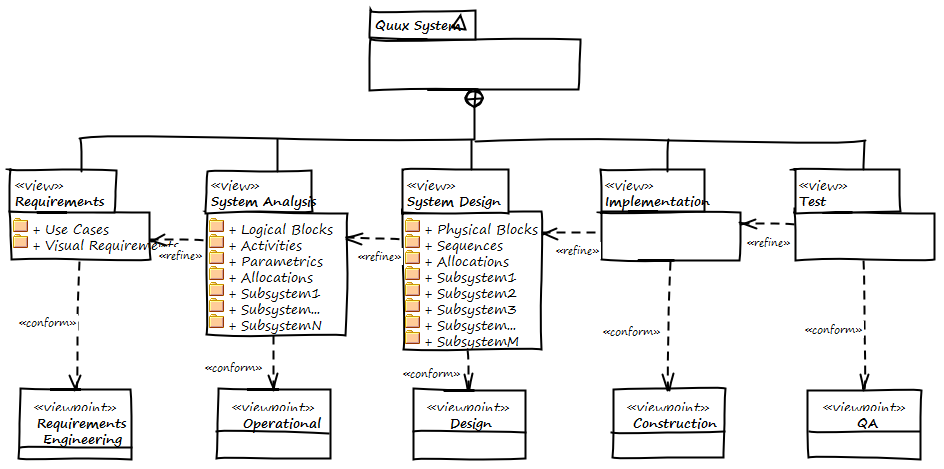
Sysml Faq What Is Sysml What Is Mbse Who Created Sysml
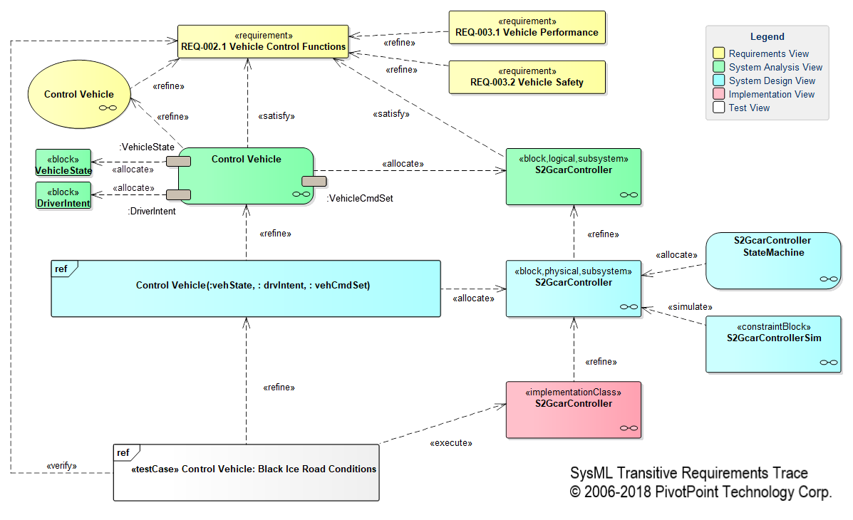
Sysml Faq What Is Sysml What Is Mbse Who Created Sysml

Sysml Solution Software Development Diagram Chart Solutions

Use Case Diagram The Basics Business Analyst Learnings Use Case Case Diagram